Buy the board: CANStepper Adapter Board on the Grafito shop.
Use these files for system understanding, enclosure design, heat-sink clearance, 3D-printed mounts, and mechanical integration of the NEMA 17–mounted CANStepper stack.
Assembly video
Physical assembly of the CANStepper stack on a NEMA 17 (board, magnet, heatsink / casing as applicable):
CANStepper assembly
Open on YouTubeIn-page previews & downloads
The system block diagram, assembly image, and mechanical drawing are rendered below. STEP models are downloadable for CAD tools (Fusion, SolidWorks, FreeCAD, Onshape, etc.).
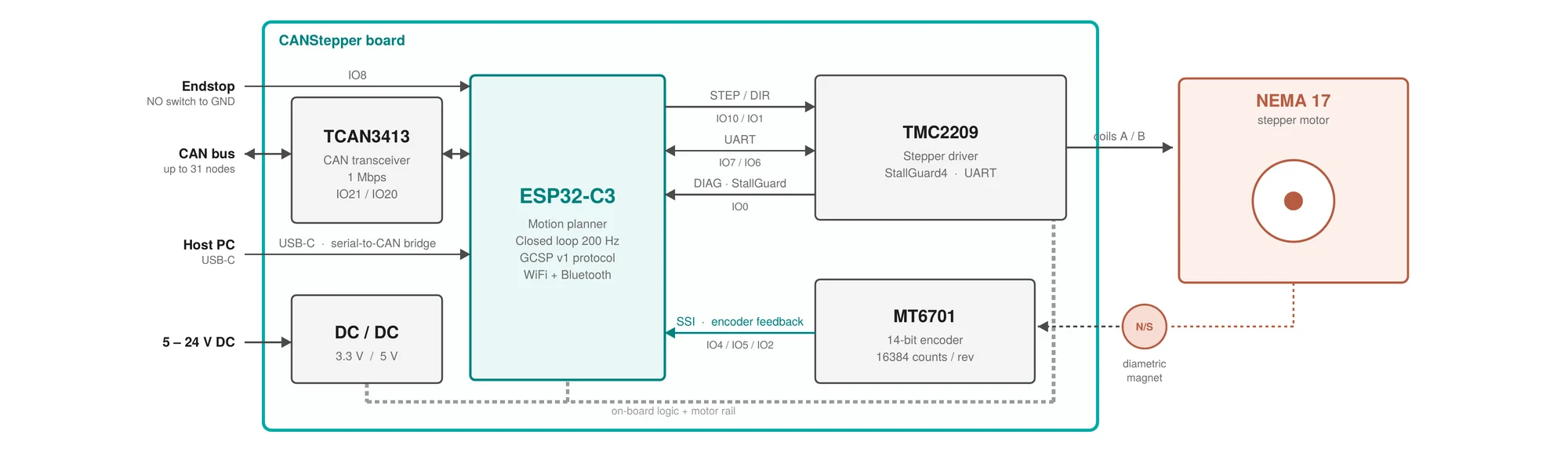
System block diagram
Board architecture: ESP32-C3, TMC2209, MT6701 encoder, TCAN3413 CAN, power, host USB, and NEMA 17.
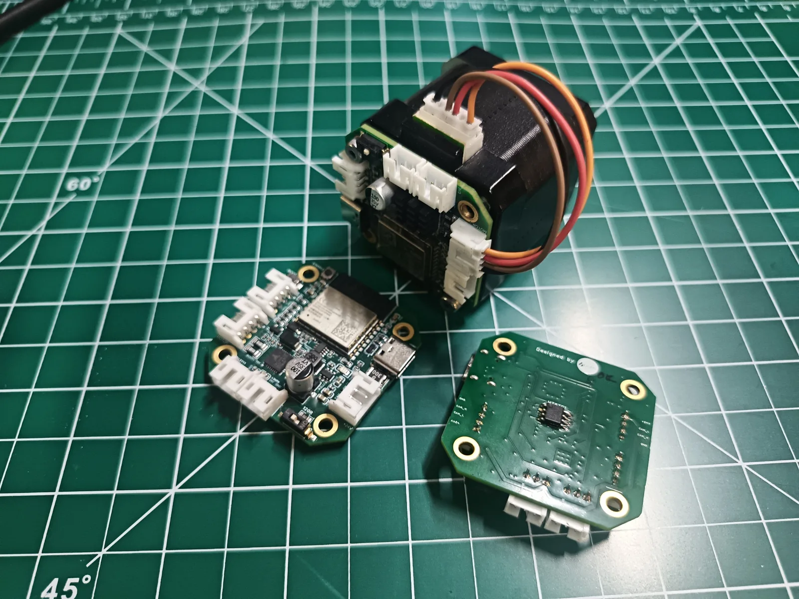
V2 assembly render
Full mechanical assembly view of the CANStepper V2 board, heatsink, and motor mount stack.
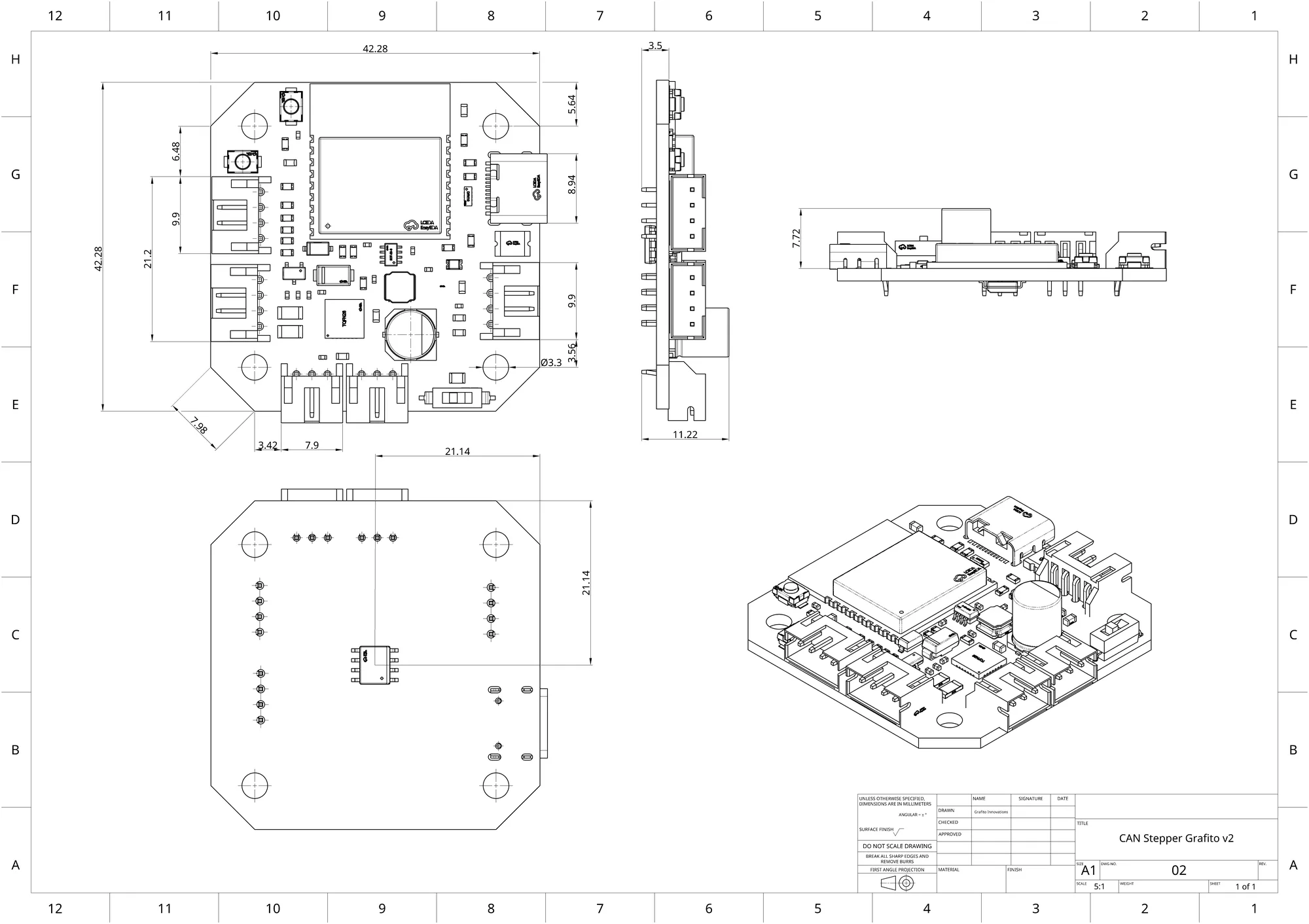
PCB mechanical drawing (PDF)
CANStepper V2 manufacturing / mechanical drawing. Preview on this page or download the PDF.
CAD & drawing downloads
System block diagram
imageBoard architecture: ESP32-C3, TMC2209, MT6701 encoder, TCAN3413 CAN, power, host USB, and NEMA 17.
V2 assembly render
imageFull mechanical assembly view of the CANStepper V2 board, heatsink, and motor mount stack.
PCB mechanical drawing (PDF)
pdfCANStepper V2 manufacturing / mechanical drawing. Preview on this page or download the PDF.
PCB 3D model (STEP)
stepFull-board STEP for CAD integration, enclosure design, and mechanical clearance checks.
Casing mount (STEP)
step3D-printed casing / mount geometry for NEMA 17 installation and enclosure fits.
Heat spreader (STEP)
stepThermal heat-spreader STEP used under / around the driver region for continuous duty.
TMC2209 heatsink (STEP)
stepHeatsink model for the TMC2209 driver package — strongly recommended for high-speed duty.
What’s included
| Asset | Format | Use |
|---|---|---|
| System block diagram | PNG / WebP | Architecture: MCU, driver, encoder, CAN, power, motor |
| V2 assembly | WebP | Visual reference for the full stack (board + thermal + mount) |
| PCB mechanical drawing | Dimensions / manufacturing drawing for CANStepper V2 | |
| PCB 3D model | STEP (~24 MB) | Full board solid model for CAD clearance and assembly |
| Casing mount | STEP | 3D-printed casing / mount geometry |
| Heat spreader | STEP | Thermal spreader geometry |
| TMC2209 heatsink | STEP | Driver heatsink for continuous / high-speed duty |
| Product brochure | CANStepper V2 brochure |
Direct paths (same files as above):
- /model-assets/canstepper-block-diagram.webp
- /model-assets/canstepper-v2-assembly.webp
- /model-assets/canstepper-v2-drawing.pdf
- /model-assets/canstepper-v2-3d-pcb.step
- /brochures/canstepper-brochure-v2.pdf
- /model-assets/canstepper-casing-mount.step
- /model-assets/canstepper-heat-spreader.step
- /model-assets/tmc2209-heat-sink.step
Assembly notes
- Mount the board on a NEMA 17 with the diametric encoder magnet centered over the MT6701 (≈1–2 mm air gap). Follow the assembly video above for the full sequence.
- Fit the TMC2209 heatsink (and heat spreader where used) before long high-current closed-loop soaks — see Hardware → Cooling.
- Use the casing mount STEP when designing machine frames or printing the included-style enclosure.
- For electrical wiring (power, CAN termination, IO8 endstop), stay on the Hardware guide.
Related
- Hardware guide — pins, power, CAN, cooling
- Motion → Dual-motor / leader–follower — encoder-mirrored dual axes (demo video)
- Quickstart — first motion
- Shop product page — buy + kit contents