Buy the board: CANStepper Adapter Board on the Grafito shop.
Board anatomy
| Component | Role |
|---|---|
| ESP32-C3 | Application MCU: motion planning, closed loop, CAN, USB |
| TMC2209 | Stepper driver, configured over UART; StallGuard4 for sensorless homing |
| MT6701 | 14-bit magnetic encoder (16384 counts/rev), read over SSI at 1 MHz |
| TCAN3413 | CAN transceiver, 1 Mbps |
The board mounts on the back of a NEMA17. The diametric magnet must sit centered over the MT6701 with roughly 1–2 mm air gap; poor magnet placement is the number-one cause of noisy angles.
System block diagram
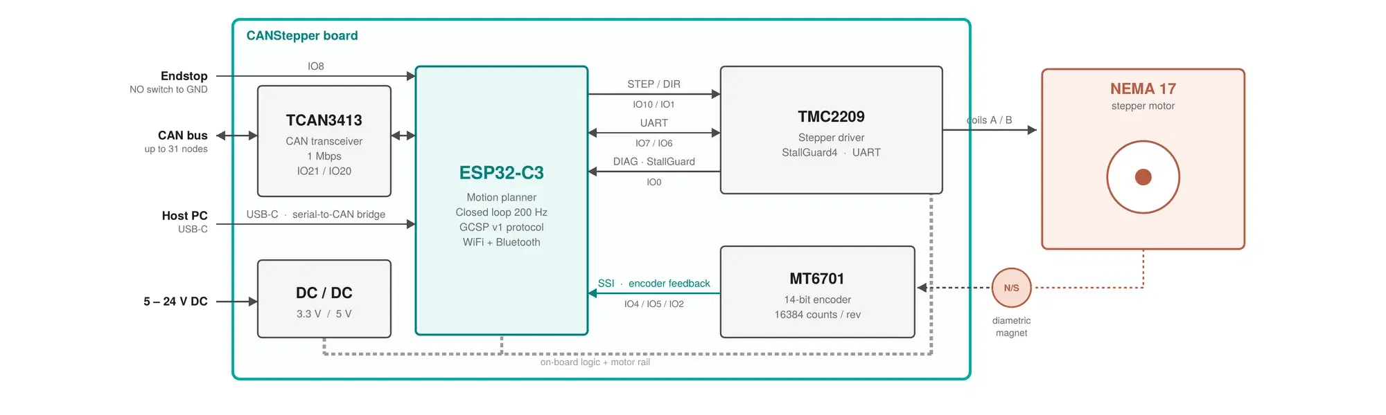
How the MCU, driver, encoder feedback, CAN transceiver, and power rails connect on the board and out to the motor.
Assembly view (V1)
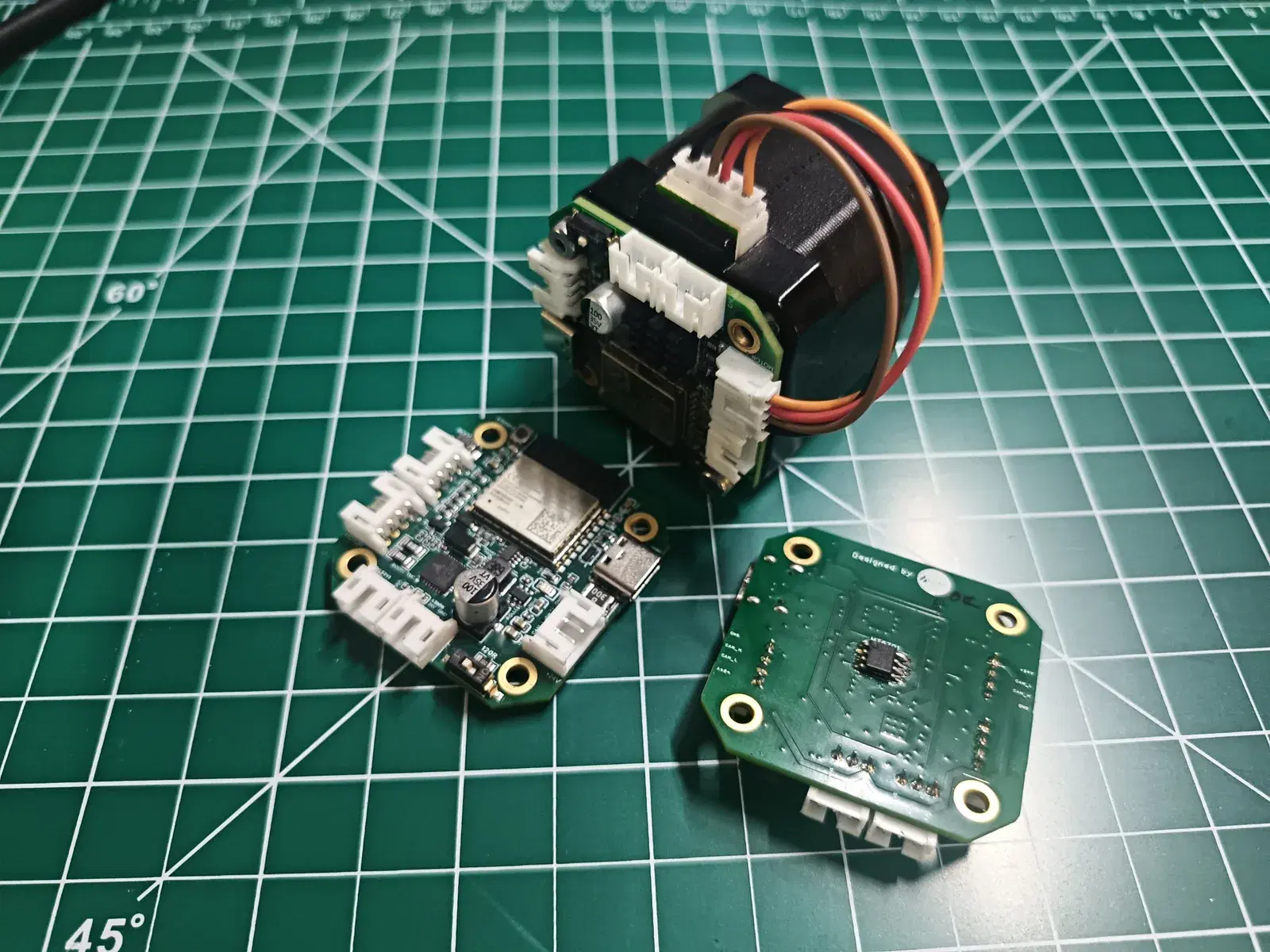
Assembly video (board on NEMA 17 — full walkthrough): YouTube — CANStepper assembly (also embedded on Mechanical CAD & drawings).
CAD downloads (PCB STEP, casing mount, heat spreader, TMC heatsink), the mechanical drawing PDF, and the block diagram (inline previews): Mechanical CAD & drawings.
TMC2209 diagnostics (firmware ≥1.4)
The host can read live TMC flags over CAN via node.get_driver_status():
- OTPW — over-temperature pre-warning (still moving)
- OT — over-temperature shutdown (motion stopped, fault code 4)
- Shorts / open-load, StealthChop vs standstill, StallGuard,
cs_actual
MCU board temperature is separate: node.get_env() → ESP32 die °C (bus
voltage is a fixed placeholder today). Full bit layout:
Protocol → DRIVER.
Cooling / heatsink (strongly recommended)
The TMC2209 dissipates heat in the package and PCB copper. At high
run_current, high cl_max_speed, and continuous closed-loop hopping, the
driver can hit:
- OTPW (pre-warning) while still moving
- OT (thermal shutdown) — coils cut,
Fault.DRIVER_OT(4) until cool +enable()
Without a heatsink (and with little airflow), that is expected under aggressive multi-axis duty — it is usually not a bad motor, bad CAN bus, or broken closed-loop tune.
| Duty | Recommendation |
|---|---|
| Bring-up, light moves | Bare board often OK |
| Production / continuous high speed | Heatsink on TMC (+ optional fan) |
| Concurrent hops ~65% / up to 4800 deg/s | Heatsink; or lower current / cruise |
Also helps: leave space around the driver, avoid sealed hot enclosures, and
watch get_driver_status().otpw during soaks before you hit OT.
STEP models for the stock TMC heatsink and heat spreader are on Mechanical CAD & drawings if you need clearance checks in CAD.
Firmware: how OTPW / OT are read
The board polls the TMC over UART (TMC2209::getStatus() / getGlobalStatus()),
packs flags into TEL_DRIVER (msg 37), and stops motion on OT or shorts.
- Full sketch (public download + preview): Firmware page
or GrafitoCANStepper_C3.ino - TMC diagnostics excerpt:
Protocol → Firmware implementation
Host-side mirror of the same bits:
d = node.get_driver_status()
if d.otpw:
    print("pre-warning — add cooling / lower current")
if d.over_temp_shutdown or d.thermal_fault:
    print("OT shutdown — wait, enable(), heatsink")
Characterization motor (docs reference)
Speed tables in Closed-loop speed tuning were measured with a PR42HS40-1204AF-02 NEMA 17 (1.8°, 1.2 A rated, 3.2 mH, 4.2 kg·cm holding, D-shaft Ø4.5×19 mm, frame 42×42×40 mm) on 24 V. Your ceiling will differ with load, supply, and motor inductance.
Pin map
| Signal | GPIO | Notes |
|---|---|---|
| CAN TX / RX | IO21 / IO20 | to TCAN3413 |
| TMC EN | IO3 | LOW = driver energized |
| STEP / DIR | IO10 / IO1 | driven by hardware pulse generator |
| TMC DIAG | IO0 | StallGuard trigger, rising edge |
| TMC UART | IO7 (TX via 1 k) / IO6 (RX) | single-wire PDN_UART |
| Encoder CLK / DO / CS | IO4 / IO5 / IO2 | MT6701 SSI |
| Endstop (HOME) | IO8 | internal pull-up, active-low by default |
Power
- Input voltage: 5–24 V DC (shop rating). Typical industrial supply is 24 V; do not exceed 24 V.
- On-board regulation derives logic rails from the main input for the ESP32-C3, encoder, and TMC logic.
- Programming / flashing requires the main power rail (typically 24 V). USB-C is for data only (CDC serial, host bridge) — USB does not power the ESP32 for programming. Connect Vin before upload or the board will not program reliably. Step-by-step: Flashing firmware.
- Motor hold and motion also need the main 5–24 V rail (not USB).
- Under very high continuous run current, motor load can stress the shared system enough that USB CDC disconnects. Prefer ~70% current for long high-speed closed-loop duty; keep bulk capacitance on 24 V healthy.
- High continuous current also heats the TMC2209 — pair power limits with a heatsink (see cooling section above).
CAN bus rules
- Linear daisy-chain (CANH / CANL / GND), twisted pair preferred; keep stubs short.
- All nodes run 1 Mbps — no baud configuration needed.
- On-board CAN termination is enabled by default. Each board ships with the 120 Ω bus termination path active via a 0 Ω jumper resistor. That is correct for a single node or for boards at the physical ends of a multi-node bus.
- Multi-drop / daisy-chain mid-nodes: only the two ends of the bus should present 120 Ω. On intermediate boards, remove the 0 Ω termination resistor so that board does not load the bus with an extra terminator. End-of-bus boards keep termination (or restore it by shorting the termination pads if the 0 Ω part was removed).
- A node powered alone (nobody to acknowledge its frames) enters bus-off and
recovers automatically once a second node appears; see
get_can_health()if a bus looks quiet.
Endstop wiring on IO8 — read this twice
IO8 is an ESP32-C3 strapping pin: it must be HIGH at reset or the chip may fail to boot.
- Use a normally-open switch to GND. Open at rest = pin HIGH = boots fine.
- A normally-closed switch that shorts IO8 to GND at power-on can brick the boot until the switch is released. If you must use NC, wire it through a series diode/OR gate so the pin is not held low at reset.
- Polarity and behavior are configurable:
endstop_active_high,endstop_enable,endstop_action(report / stop / stop + zero).
Recommended active-low circuit:
3.3V ---- 10k ----+---- ≤330 Ω ---- IO8 (HOME / GPIO8)
                  |
               [NO switch or optical NPN OC] ---- GND
ESP32-C3 strapping (datasheet Table 3-3): GPIO8 is sampled only at reset. SPI boot wants GPIO8 = 1 (HIGH). After boot it is a normal GPIO. Do not hold HOME low at power-on.
Firmware enables an internal pull-up as well. A common mistake is:
3.3V -- 10k -- junction -- 4.7k -- GPIO8
                 |
              (sensor that never reaches 0 V)
If the sensor only swings ~2.3 V ↔ ~3.3 V, that is mid-rail — the
chip’s digital input will not toggle. Target multimeter on GPIO8:
idle ≈ 3.3 V, active ≈ 0 V (active-low) or idle ≈ 0 V, active
≈ 3.3 V (then set endstop_active_high=1).
fw ≥1.5 STATUS reports raw GPIO8 HIGH/LOW for debugging (home_raw_high).
Sensorless (no switch) uses StallGuard on DIAG / IO0 — see Homing and endstops.
Validate the pin with:
PYTHONPATH=. python3 examples/endstop_monitor.py /dev/ttyACM0 1 30
PYTHONPATH=. python3 examples/home_endstop.py /dev/ttyACM0 1 -1
IO2 (encoder CS) and IO9 (BOOT button) are also strapping pins; the board pulls them correctly — just don't add external loads to them.
The other strapping consequence
Because IO9 is the BOOT button, "hold a button at power-on" schemes are unreliable on the C3 (holding it enters the serial bootloader instead). Node addressing is therefore done over USB — see the quickstart.